|
Direct3D Basics
with Examples in C/C++ |
|
Prof. David Bernstein |
| Computer Science Department |
| bernstdh@jmu.edu |
|
Direct3D Basics
with Examples in C/C++ |
|
Prof. David Bernstein |
| Computer Science Department |
| bernstdh@jmu.edu |
DXUT orHRESULT IDirect3D9::CreateDevice(UINT adapter, D3DDEVTYPE type, HWND window, DWORD flags, D3DPRESENT_PARAMETERS* params, IDirect3DDevice9** returnedDevice)
D3DDEVTYPE_HAL)
D3DDEVTYPE_REF)
D3DCREATE_SOFTWARE_VERTEXPROCESSING
D3DCREATE_HARDWARE_VERTEXPROCESSING
D3DCREATE_MIXED_VERTEXPROCESSING
D3DCOLOR_ARGB)
struct for a vertex
D3DFVF_XYZ
D3DFVF_DIFFUSE,
D3DFVF_SPECULAR
D3DFVF_NORMAL
D3DFVF_PSIZE
// Specify the struct for a vertex
struct CUSTOMVERTEX
{
    float x, y, z;
        DWORD color;
};

// Specify the flexible vertex format (FVF) for the struct above
#define D3DFVF_CUSTOMVERTEX (D3DFVF_XYZ | D3DFVF_DIFFUSE)


// Color Definitions
DWORD colorBlue   = 0xFF0000FF;
DWORD colorGold   = 0xFFC2A14D; // JMU Gold
DWORD colorGray   = 0xFFAAAAAA;
DWORD colorGreen  = 0xFF00FF00;
DWORD colorPurple = 0xFF450084; // JMU Purple
DWORD colorRed    = 0xFFFF0000;
DWORD colorYellow = 0xFFFFFF00;

// Create the vertex elements
CUSTOMVERTEX vertices[] =
{
        {-1.0f, 1.0f,-1.0f, colorBlue},
        { 1.0f, 1.0f,-1.0f, colorBlue},
        {-1.0f,-1.0f,-1.0f, colorBlue},
        { 1.0f,-1.0f,-1.0f, colorBlue},

        {-1.0f, 1.0f, 1.0f, colorGold},
        {-1.0f,-1.0f, 1.0f, colorGold},
        { 1.0f, 1.0f, 1.0f, colorGold},
        { 1.0f,-1.0f, 1.0f, colorGold},

        {-1.0f, 1.0f, 1.0f, colorGray},
        { 1.0f, 1.0f, 1.0f, colorGray},
        {-1.0f, 1.0f,-1.0f, colorGray},
        { 1.0f, 1.0f,-1.0f, colorGray},

        {-1.0f,-1.0f, 1.0f, colorGreen},
        {-1.0f,-1.0f,-1.0f, colorGreen},
        { 1.0f,-1.0f, 1.0f, colorGreen},
        { 1.0f,-1.0f,-1.0f, colorGreen},

        { 1.0f, 1.0f,-1.0f, colorPurple},
        { 1.0f, 1.0f, 1.0f, colorPurple},
        { 1.0f,-1.0f,-1.0f, colorPurple},
        { 1.0f,-1.0f, 1.0f, colorPurple},

        {-1.0f, 1.0f,-1.0f, colorRed},
        {-1.0f,-1.0f,-1.0f, colorRed},
        {-1.0f, 1.0f, 1.0f, colorRed},
        {-1.0f,-1.0f, 1.0f, colorRed}
};
IDirect3DVertexBuffer9)
HRESULT CreateVertexBuffer(UINT size, DWORD usage, DWORD fvf, D3DPOOL pool, IDirect3DVertexBuffer9** vertexBuffer, NULL)
        // Create the vertex buffer
        d3dDevice->CreateVertexBuffer(24*sizeof(CUSTOMVERTEX),0,  D3DFVF_CUSTOMVERTEX,
                                  D3DPOOL_DEFAULT, &vertexBuffer, NULL );

        // Declare the source data for the buffer
        VOID* data = NULL;

        // Lock the vertex buffer
    vertexBuffer->Lock( 0, sizeof(vertices), (void**)&data, 0 );

        // Copy the vertices into the buffer
    memcpy(data, vertices, sizeof(vertices));

        // Unlock the vertex buffer
    vertexBuffer->Unlock();


HRESULT IDirect3DDevice9::DrawPrimitive(D3DPRIMITIVETYPE type, UINT startVertex, UINT primitiveCount)
HRESULT IDirect3DDevice9::DrawIndexedPrimitive(D3DPRIMITIVETYPE type, INT offset, UINT minIndex, UINT numVertices, UINT startIndex, UINT count)

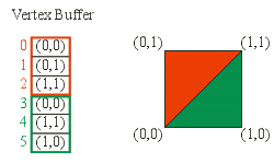
device->DrawPrimitive(D3DPT_TRIANGLELIST,
                      0,                  // startVertex
                      2);                 // primitiveCount

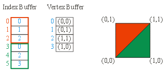
device->DrawIndexPrimitive(D3DPT_TRIANGLELIST,
                           0,                  // offset
                           0,                  // minIndex
                           4,                  // numVertices (in total)
                           0,                  // startIndex
                           2);                 // primitiveCount
IDirect3DDevice9::BeginScene()
IDirect3DDevice9::EndScene()
IDirect3DDevice9::Present(NULL, NULL, NULL, NULL)
HRESULT IDirect3DDevice9::SetStreamSource(UNIT streamNumber, IDirect3DVertexBuffer9* streamData, UINT offset, UINT stride)
HRESULT IDirect3DDevice9::SetFVF(DWORD fvf)
/**
 * The function that is called when the scene needs to be rendered
 */
void CALLBACK paint(IDirect3DDevice9* d3dDevice,
                                        double time, float elapsedTime,
                                        void* userContext )
{
    HRESULT hr;

    // Clear the render target and the zbuffer
    V(d3dDevice->Clear(0, NULL, D3DCLEAR_TARGET | D3DCLEAR_ZBUFFER,
                           D3DCOLOR_ARGB(0, 0, 0, 0), 1.0f, 0) );


    // Render the scene
    if( SUCCEEDED(d3dDevice->BeginScene()))
    {
                // Transform the model
                D3DXMATRIX rotate, translate, world;

                D3DXMatrixTranslation(&translate, 0.0f, 0.0f, 5.0f );
                D3DXMatrixRotationY(&rotate, rotateY);

                D3DXMatrixMultiply(&world, &rotate, &translate);
                d3dDevice->SetTransform(D3DTS_WORLD, &world );


                // Starting to define the scene
                d3dDevice->BeginScene();

                // Bind the vertex buffer to the device
                d3dDevice->SetStreamSource(0, vertexBuffer, 0, sizeof(CUSTOMVERTEX));

                // Setup the vertex shader
                d3dDevice->SetFVF(D3DFVF_CUSTOMVERTEX);

                // Draw the various shapes (two triangles for each face)
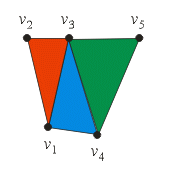
                d3dDevice->DrawPrimitive(D3DPT_TRIANGLESTRIP,  0, 2);
                d3dDevice->DrawPrimitive(D3DPT_TRIANGLESTRIP,  4, 2);
                d3dDevice->DrawPrimitive(D3DPT_TRIANGLESTRIP,  8, 2);
                d3dDevice->DrawPrimitive(D3DPT_TRIANGLESTRIP, 12, 2);
                d3dDevice->DrawPrimitive(D3DPT_TRIANGLESTRIP, 16, 2);
                d3dDevice->DrawPrimitive(D3DPT_TRIANGLESTRIP, 20, 2);

        V(d3dDevice->EndScene());
    }
}
D3DXMATRIX
D3DXMatrixRotation*(),
D3DXMatrixReflect(),
D3DXMatrixScaling(),
D3DXMatrixTranslation(), etc...
HRESULT IDirect3DDevice9::SetTransform(D3DTRANSFORMSTATETYPE type, CONST D3DMATRIX* m)
type is D3DTS_VIEW,
D3DTS_PROJECTION, or D3DTS_WORLD
D3DXMATRIX* D3DXMatrixLookAtLH(D3DXMATRIX* mOut, CONST D3DXVECTOR3* eye, CONST D3DXVECTOR3* at, CONST D3DXVECTOR3* up) where the
LH indicates "left-handed"
D3DXMATRIX* D3DXMatrixRotationYawPitchRoll(D3DXMATRIX* mOut,FLOAT yaw, FLOAT pitch, FLOAT roll)
where the pitch is around \(x\), the yaw is around \(y\), and the roll is around \(z\)
D3DXMATRIX* D3DXMatrixOrthoLH(D3DXMATRIX* mOut, FLOAT w, FLOAT h, FLOAT znear, FLOAT zfar)
D3DXMATRIX* D3DXMatrixPerspectiveFovLH(D3DXMATRIX* mOut, FLOAT fovy, FLOAT aspect, FLOAT znear, FLOAT zfar)
/**
 * The function that is called when the mouse is
 * moved or clicked
 */
void CALLBACK mouseEvent(bool leftDown, bool rightDown, bool middleDown,
                                                 bool side1Down, bool side2Down,
                                                 int wheelDelta, int x, int y, void* userContext)
{
        if (rightDown)
        {
                rotateY -= (float)D3DX_PI/10.0f;
        }
        else if (leftDown)
        {
                rotateY += (float)D3DX_PI/10.0f;
        }
}